Design Formulation
Taking into consideration the preliminary findings, the noise sources were explored to understand how to minimize their effects. The fluidics subsystem, comprising of the pump and the flow channels, is responsible for delivering solution into the flow cell where the particle detection occurs and then removing the waste solution. This subsystem needs modifications to help eliminate the current problems of bubbles forming inside the flow cell that can disturb the optical readings taken by the spectrometer. The shape of the flow chamber over the chip should be optimized to prevent uneven flow and maximize mixing efficiency. The optics subsystem consists of the spectrometer that emits the light signal and also collects the reflected light hovers over the flow cell, allowing ambient light to interfere with the light signal. By stabilizing these subsystems, the sensitivity of the entire system will increase, making the detection limit of the system lower and decreasing the time for the chip to reach saturation with the proteins. Fewer proteins are then needed to get the data needed to understand the kinetics and identify the protein, which is important if there is only a small sample of the protein that needs to be processed.
Final Design Solution
Using a decision matrix to compare the important design criteria of possible design solutions, we arrived at our final prototype design (Figure 1 and 2).
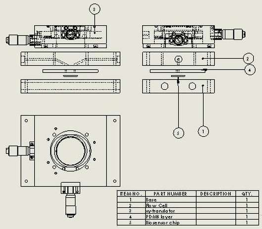
Figure 1. Final prototype design.
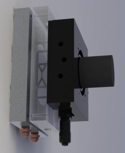
Figure 2. 3D model of final prototype design.
Compared to the other designs, our final design utilizes the most
standard parts. The Thorlabs translator allows the user to have constant
and precise control over the position being measured in the X and Y
direction, allowing for interchangeability and variability with parts.
Through the attachment of the flow cell directly to the spectrometer via
the Thorlabs translator, possible user alignment error between the flow
cell and the spectrometer as well as ambient light issues are removed,
allowing for steadier readings.
Simultaneously, the attachment of the flow cell to the spectrometer allows the system to be held vertically instead of horizontally, so that the fluid flows vertically over the chip, against gravity. This allows for efficient and automatic bubble removal through a simple orientation change. The flow channels have also been changed to produce softer angles, aiding the removal of bubbles, ensuring that they do not become trapped in the chamber and interrupt data collection.
After consulting with other Sailor Lab group members, the need for a temperature controlled system became more significant, especially for experiments trying to mimic in vivo conditions and for gas sensing. The base layer, which the chip lays on top of, is made of aluminum to act as a method for temperature control. A circulating chiller flows constant temperature water through channels drilled in the base layer, providing a large thermal mass to maintain a set constant temperature of the chip.
Lastly, the chamber shape has been changed from the existing circular chamber (Project Details - Figure 2) to a linear channel (Figure 3), with inlets and outlets at the farthest ends. The benefits include the elimination of irregular flow properties and more uniform data acquisition over a large area of the chip. The channel chamber shape also helps in the removal of bubbles formed in the flow. The newly design chamber is formed by a PDMS mold placed between the flow and base layers. The use of a master to create the PDMS layer allows for the production of the PDMS layer with possibilities for thickness modifications for future experiments. Soft lithography of the PDMS layer may be needed in certain application of the flow system depending on the analyte being tested.
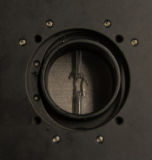
Figure 3. New linear flow channel shape.
Combining
these separate solution to each of the identified problems into one
design allows the redesigned flow cell to be buffered against the noise
generated from flow, light, user setup, and temperature.
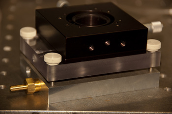
Figure 4. Fabricated final prototype design.
-Sid Kundu
